How to Interpret Hydraulic Control Schematics, for Beginners
Hello hydraulics fans, Tomas here with a follow-up on the V14 Motor Testing Video we put up last week:
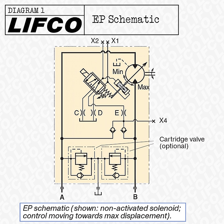
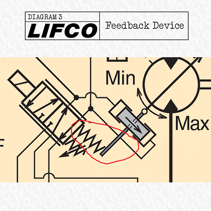
Tomas: Hi Fraser, on the V14 Testing video, you mentioned that we'd have a post about schematics on the EO vs EP Controls. I think I found the correct ones in the manual but am having a hard time telling the difference between the two based on this schematic alone. How do you go about interpreting these two? (Figure 1+2)
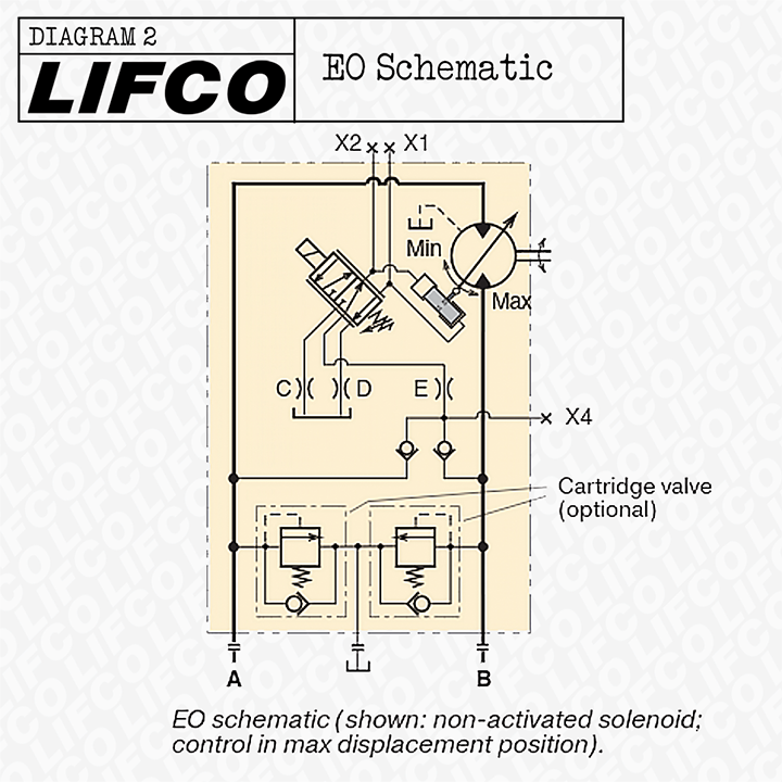
Fraser: The main difference we see is that there is a lack of feedback from the setting piston to the servo valve spool (Figure 3). Page 13 of the manual has a great diagram of it. The removal of a feedback device means that the valve does not know when to stop shifting. This creates the effect of turning something proportional into a "bang-bang" valve. Meaning that it is fully in one position/side or the other.
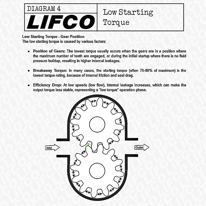
Tomas: You also mentioned gears meshing (in gear motors) in the V14 Video. How does meshing like this impact torque? You said a piston motor might be better for certain applications like a winch or crane because there is no meshing, why is this?
Fraser: Noble is making you a diagram to show the concept of meshing, it is attached below. (Figures 4,5, & 6)
Tomas: So what do these show us in regards to meshing, and how does this impact torque?
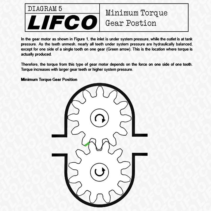
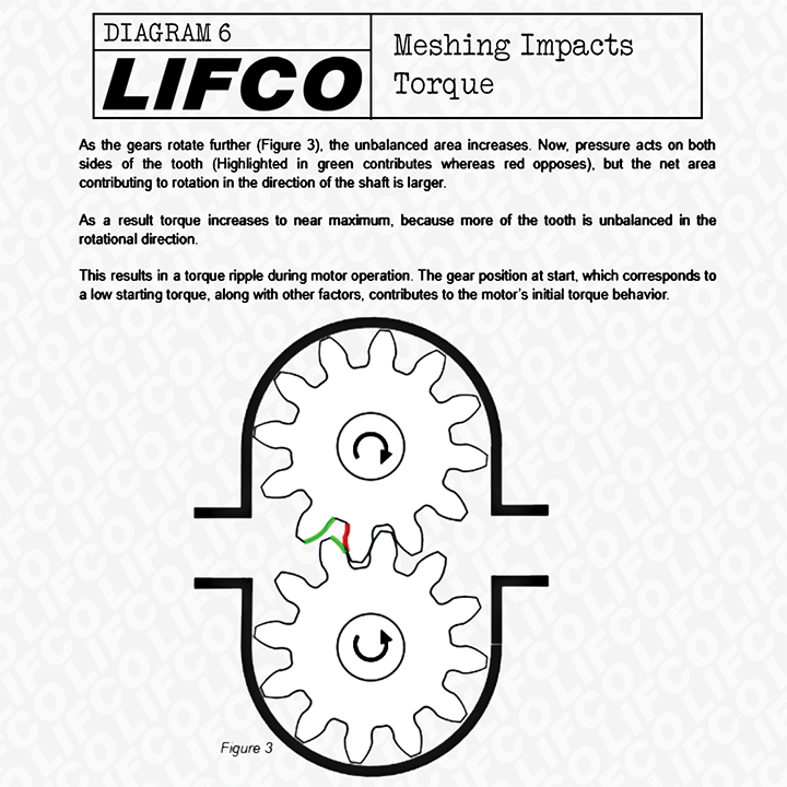
Fraser: PSI = pounds per square inch. It means that pressure exerts a force on all surface areas. If the surface amount changes, then the total amount of force changes. In this diagram , we care about just the difference between forces turning it one way to the forces turning it the opposite way. Because that is what is going to make the gears spin. We can see that value changing at various positions. Thus: irregular motor torque.
Tomas: Ok I think that makes sense, and because pistons always have the same amount of surface area in contact with the swashplate, their torque is always consistent?
Fraser: They have more consistent. Still not perfect. There can still be pulsations in a piston-type pump and motor. That is why Linde pumps have the option for a "SPU" (we call them 'spuds') which suppresses them. Parker has some options for a "ripple chamber" , which does the same thing. We can't put flow meters too close to a piston pump or the pulsations distort it. But all of these seem to be less problems on the motor side.
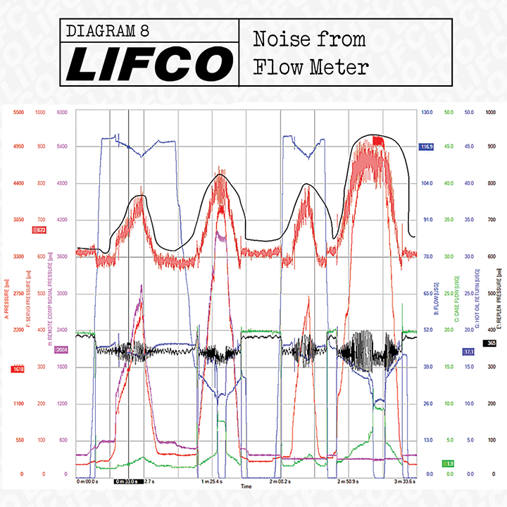
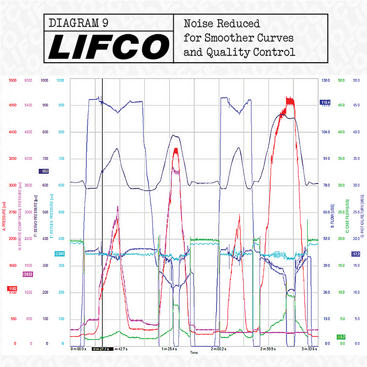
Tomas: How/why do flow meters produce distortion? I thought they were a fairly simple gauge?
Fraser: The flow meters are measuring, not producing. But they have a turbine in them and it can accelerate and decelerate with each pulse from the pistons . It makes for a very distorted graph. We can clean up the graph after by applying some statistical techniques to smooth things out, but that is annoying to do repeatedly (Figure 8 &9)
Tomas: If gear motors have this problem providing consistent start-up torque, why would somebody choose one over an axial or radial piston motor? Are there any applications where gear motors are better than other types?
Fraser: Cheap. That's it.
Tomas: Are there any applications where you would actually recommend a gear motor over a piston one? I imagine some applications do not require consistent start up torque, and you could probably get away with going with the cheaper option.
Fraser: Very small motors. There are some gear motors that can fit in the palm of your hand. Those will not get replaced by a vane or piston motor.
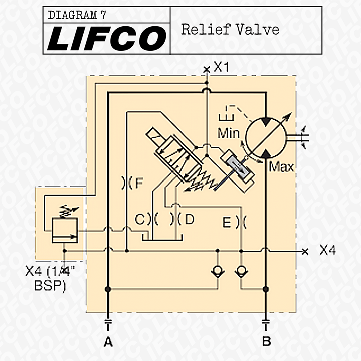
Tomas: Back to EO Vs EP Controls, the only difference was that feedback device you noted earlier? I saw this other schematic with this block on the left side, not sure if that is part of the control or not. (Figure 7)
Fraser: Yes, now what was the function of the component on the left of your original picture?
Tomas: I think it is meant to signal to the motor to stop shifting, correct?
Fraser: It is a relief valve, which is a type of pressure valve, that is relieving at an adjustable amount. There is an arrow on the swashplate sliding assembly that points this motor to max. Which means the control pressure reduces the displacement towards minimum. This is going to relieve the pressure in that control, meaning it is moving it back to max displacement until the pressure is less than what the relief valve is set to. So you have the swashplate sliding assembly that wants to be at max displacement, then you have the control that will tell it to move towards minimum displacement, and then there is that pressure cut off that is making sure that the control doesn't move itself too far to minimum. The wonders of hydraulics.
See our Stock of V14 Motors on our Website